
Electronics installation
Connecting all hardware components for the development kit is pretty straightforward. For this prototype version we have chosen to use as many plug-and-play and of-the-shelf products as possible. So we use an IKEA plant care kit in combination with basic Grove sensors.
Connect the electronic components
For the development kit we use a raspberry pi and an Arduino. The Raspberry runs on 3.3v and the Arduino on 5v. The idea for future version is that you could attached multiple Arduino’s (AstroPlant Modules) with one Raspberry. This means that the Raspberry is the host and the Arduino the slave.
Since there are limited USB ports on the Raspberry, and the fact that there is a possibility to connect up to 128 slaves we chose to use the I2C connection. Using I2C we can connect the two directly, without using a Level Logic Converter. The reason it works is because the Arduino does not have any pull-ups resistors installed, but the P1 header on the Raspberry Pi has 1k8 ohms resistors to the 3.3 volts power rail. Data is transmitted by pulling the lines to 0v, for a “high” logic signal. For “low” logic signal, it’s pulled up to the supply rail voltage level. Because there is no pull-up resistors in the Arduino and because 3.3 volts is within the “low” logic level range for the Arduino everything works as it should [Source].
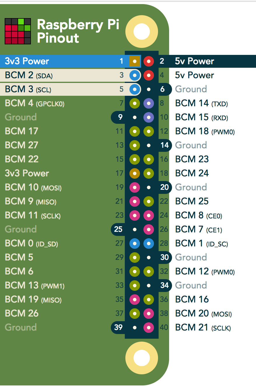
Note that the built-in pull-up resistors are only available on the Pi’s I2C pins: Pins 3 (SDA) and 5 (SCL). On the Arduino Uno, the I2C pins are pins A4 (SDA) and A5 (SCL).
The arduino is powered by the raspberry. Connect GND and 5V with the GND and 5V of the Arduino.
Component connection list
- Connect RPi 3 (SDA) with Arduino header pin A4
- Connect RPi 5 (SCAL) with Arduino header pin A5
- Connect RPi 4 (5V) with Arduino header pin 5V
- Connect RPi 6 (GND) with Arduino header pin GND
- Connect the Digital Light Sensor with Grove I2C
- Connect the Barometer with Grove I2C
- Connect the Digital Infrared Temperature sensor with Grove I2C
- Connect the Water sensor with Grove D8
- Connect the DS18B20 digital temperature sensor: Solder the wires to the Grove connector: red wire to 5V, black wire to GND, yellow wire for data. Connect the 4.7kOhm resistor with + and DATA. Connect to Grove D7
- Connect the LED Strip: Solder the wires to a Grove connector. Connect to D6
- Connect the Cooling fan: Solder the wires to a Grove connector. Connect to D5
Software
Development software tools
Current development is being done on Mac OSX, we have used the following software to create the AstroPlant Dev Kit:
Raspberry Pi
Raspberry Pi Installation
We use a Raspberry Pi Zero W. This is a low cost and small micro-computer with onboard wifi and bluetooth. The Raspberry is the heart of the AstroPlant. For the prototype, we have to hardcode the wifi credentials for the location where the AstroPlant is placed. It is possible to add multiple wifi access points. We use ApplePiBaker to install Raspbian Jessie Lite (download link) to the sd-card.
Raspberry Pi Configuration
We need to add and configure some files in the boot partition of the sd-card. This is to make sure the Raspberry will boot up in the right way.
- Insert the sd-card in your computer.
- In the boot partition of the sd-card, add to the bottom of the
config.txtfiledtoverlay=dwc2on a new line, then save the file. - Add a new blank file calles
sshto the root of the boot partition. This is to enable SSH access. - Open
cmdline.txtand insertmodules-load=dwc2,g_etherafterrootwait. This configuration is very picky with its formatting! Each parameter is separated by a single space (it does not use newlines). -
Add
wpa_supplicant.confto the root of the sd-card. When starting up, Raspbian will use this file to setup the wifi. This version of the raspberry only works with 2.4GHz networks (not 5GHz!). Use the following contents (with your own credentials):country=GB ctrl_interface=DIR=/var/run/wpa_supplicant GROUP=netdev update_config=1 network={ ssid="WorkSSID" psk="passwordWork" id_str="work" } network={ ssid="HomeNetworkSSID" psk="passwordHome" id_str="home" }
Access from local computer
At this point, it can be difficult to obtain the ip-address of the device. For now, it is needed to look up the ip-address of ‘raspberrypi’ in the router network list. This means you have to log into the router and look up the device. When you know the ip-address you can use SSH to login: pi@192.x.x.x with the default password ‘raspberry’.
Initialization
To make it easier to identify the kit on the network, it is better to change the hostname of the device. The default hostname is ‘raspberrypi’. Let’s change that to ‘astroplant001’
  sudo apt-get update
  sudo apt-get upgrade
  sudo raspi-config
  --> advanced: expand filesystem
  --> Localization options, change timezone, : en_GB.UTF_8
  --> change hostname: astroplant001
  --> finish
Using the avahi-daemon package makes it possible to access the device using astroplant001.local. Using this method, you do not need to know the ip-address of the network.
  sudo apt-get install avahi-daemon
  sudo reboot -n
Enable I2C
To make communication between the raspberry and arduino possible, we need to enable I2c Communication on the Raspberry. This is disabled by default.
sudo apt-get install -y python-smbus i2c-tools
sudo raspi-config
  7 Advanced Options --> expand filesystem
  4 Interfacing Options --> P5 I2C --> <yes>
  <Finish>
sudo reboot -n

# Check if I2C is enabled at the rpi0:
sudo i2cdetect -y 1
Install NodeJS
wget http://node-arm.herokuapp.com/node_latest_armhf.deb
sudo dpkg -i node_latest_armhf.deb
node -v
Install Johnny-five
https://github.com/nebrius/raspi-io/wiki/Getting-a-Raspberry-Pi-ready-for-NodeBots
sudo apt-get install git wiringpi
Download the AstroPlant firmware
Clone the latest version of the firmware. We put the code in /home/pi/astroplant. Also add the right certificates for AWS.
  cd
  git clone http://github.com/urbanlink/astroplant-prototype astroplant
  nano /certs/xxxxxx-certificate.pem.cert >> copy cert
  nano /certs/xxxxxx-private.pem.key >> copy cert
  nano /certs/123.cert >> copy cert
Boot the node server at startup
We use the ‘forever’ module to keep the server running:
sudo npm install -g forever
crontab -u pi -e
@reboot /usr/bin/sudo -u pi -H /usr/local/bin/forever start -e /home/pi/astroplant/logs/error.log -l /home/pi/astroplant/logs/logs.log -a /home/pi/astroplant/raspberry/server/server.js
--> ctrl-x
--> yes
sudo reboot -n
Log rotate
Make sure the logs are properly rotated, or they will completely fill the storage on the raspberry
sudo nano /etc/logrotate.d/astroplant-server
/home/pi/astroplant/logs/server.log {
  #size 50k
  daily         # how often to rotate
  dateext       # adds date to filename
  missingok     # don't panic if the log file doesn't exist
  rotate 10     # max num of log files to keep
  compress      # compress rotated log file with gzip
  delaycompress
  notifempty    # ignore empty files
  #create 644 root
  copytruncate  # needed for forever to work properly
  dateformat %Y-%m-%d.
}
Arduino
To make the Arduino go to work, we have to upload the sketch (with required libraries) to the board.
- Connect Arduino to your computer
- Make sure you have a connection in the Arduino IDE
- Open the Arduino folder from the AstroPlant codebase
- Verify and upload the sketch
- Done!
Arduino - RPi communication
The Raspberry and Arduino are connected by I2C. The Arduino has a continuous polling system for the sensors. Every minute (or a different timeframe you configure) the latest values of the sensors are being polled and stored in the Arduino. The software on the Raspberry has a polling interval as well. Based on the user’s setting, the Arduino is polled for the latest values of the sensors. This communication is done using the I2C bus. The Arduino responses to an I2C bus request of the Raspberry and sends back the data.
DONE!
After a reboot, the system should be running and sending its data to the AstroPlant backend.
Debugging tips
- You can connect the arduino to your computer and open the serial monitor.
- On the Raspberry, logs are streamed to /home/pi/logs
- You should be able to see a status page at http://astroplant001.local